Latest Products





Contact Us

CHINA
ADD: ChaoYangNan Str, 300m to BaoCang Express Way Exit, BaoDing, HeBei, China
TEL: +86-312-2090169/2090165
FAX: +86-312-2090165
Email: sales02@metowd.com

IRAN
ADD: No.3 - Golshid9 St. - Nakhlestan Blvd. - Shams abad industrial Zone -40km Tehran Qom Freeway - Tehran - Iran
Postal Code: 1834175977
Tel: 00982156231607-8
Mob: 00989121350509
Email: atiravesh@yahoo.com

Germany Design & Development Office
Germany Design & Development Office
ADD: Wellensiek 111, 33619 Bielefeld Deutschland, Germany
Tel: 0049 521 9890 170
Mob: 0049 163 5149 622

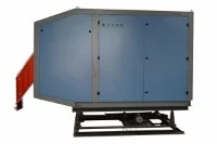
SIC Pipe Welding Machine
The SIC pipe welding machine is one of our main products. It is the third generation welder developed by our company firstly in this industry in China. 5.2 Main technical advantages of SIC High-efficiency switch welder 5.2.1 Simple line and convenient installation During installation of the...
Description
| Description |
The SIC pipe welding machine is one of our main products. It is the third generation welder developed by our company firstly in this industry in China.


5.2 Main technical advantages of SIC High-efficiency switch welder
5.2.1 Simple line and convenient installation
During installation of the equipment, it is only necessary to connect the three-phase power supply with the main circuit cables of the SIC High-efficiency switch welder. There are less than ten connecting line between the three-phase power and the SIC High-efficiency switch welder. There are also a small number of connecting line between the SIC High-efficiency switch welder and the operation desk. In the event that the user provide good cooperation on the site, the installation of the entire power supply can be completed within two days.
5.2.2 Complete protection and easy maintenance
1) Main control board: overcurrent protection, open circuit protection, temperature protection, water shortage protection, water temperature protection, over voltage protection, low power supply voltage protection, power supply indication, main circuit connection indication, and safety start/stop control circuit.
2) Inverter trigger board: high phase protection, low phase protection, frequency over-limit protection, overvoltage protection, low power supply voltage protection of control board .
3) Power module board: high water temperature protection, low power supply voltage protection, pulse loss protection, power module (SIC) damage protection.
With the power module board as the lowest level, the alarm information in the above-mentioned three parts of protection will be passed to the inverter control board through fast optocoupler, and then sent to the main control board after corresponding processing of control board in the event of any fault in the module. 5.2.3 Small harmonic interference and no pollution to the power grid
Three-phase AC power supply coverts the alternating current to the direct current through the full-bridge rectifier circuit. The line is equipped with a number of well-matched filter networks, leading to a very few harmonic components during operation of the SIC High-efficiency switch welder. The power factor may reach 0.96 or more.
5.2.4 Safety without high pressure and no sparking by sensor to steel pipe
The new generation of SIC High efficiency switch welder uses low-voltage high-current resonant technology to enable the sensor to obtain the appropriate output voltage, which avoid the sparking between the sensor and the pipe, and increase the stability of the equipment.
5.2.5 High efficiency and remarkable energy conservation
Loss of power device is divided into conduction loss and switching loss. Power IGBT and SIC devices have very low conduction loss. However, since parasitic interelectrode capacitance exists among the pins of the power electronic devices, the charge on the capacitor will be converted into thermal energy for dissipation during device switching. This undoubtedly increases the device heating, and reduces the machine efficiency and power stability. As the operating frequency increases, the switching loss of device will reach the unacceptable level. It is the main reason for limiting the operating frequency of power electronic device. Therefore, people have developed the soft-switching technology. At present, the main soft-switching technology is zero-voltage switching technology (ZVS) and zero-current switching technology (ZCS). The switching loss of the power device can be very considerable under high-frequency switching situation . Because ZVS technology is to realize the switching when the drain-source voltage of the SIC tube is zero, the stored charge of the inter-electrode capacitor has already been discharged with the resonant circuit, so the switching loss can be reduced to zero. However, the ZCS technology can not decrease the switching loss to zero. The power supply uses advanced zero-voltage switching (ZVS) technology, which almost completely eliminates the switching loss of power devices under the high frequency. When the sensor and the unit are adjust the optimal status, the machine efficiency can reach up to 90%.
5.2.6 Small welding spatter and good welding quality
Thanks to the replacement of thyristor with IGBT and fast recovery diode, the new generation of SIC High-efficiency switch welder enjoys stable output, the weld presents a bright line during welding, without a lot of sparks. So, the quality of the corresponding weld is considerably increased. The internal weld is basically a straight line, which is the main reason for high-precision welded pipe to widely use the SIC High-efficiency switch welder.
5.2.7 Load matching technology (optional)
For the same SIC High-efficiency switch welder, as the unit changes steel pipe specifications and uses different sensors, the adjustment of unit status or change of welding method will cause change in the equivalent impedance of load, resulting in load matching problem. The purpose of load matching is to equalize the equivalent impedance of the load with the required impedance (RN=UN/IN) of the welder so as to ensure that the welder can output its nominal rated power under different load conditions. Good load matching is the guarantee for welder power output, reliable operation and high-efficiency operation. The consequence of load mismatch, regardless of light load or heavy load, is that the welder can not output the nominal rated power, resulting in great waste of energy. Traditional load matching methods: after shutdown, manually change the resonant tank capacitance and the sensor parameters, etc. For the new generation of switch welder, the tank circuit inductance parameters may be changed without shutdown to achieve load matching, which can greatly improve the operation efficiency of the welder.
5.3 Comparison of SiC high-efficiency switch welder and High Efficiency Switch Welder
Name | Type No. | RDS(on) (Ω) | VDS | TC =25℃ | TC =100℃ | Td(on) | Tr | Td(off) | Tf |
MOSFET | IRFP460 | 270mΩ | 500V | 20A | 13A | 18 | 59 | 110 | 58 |
SIC | UJ3C120040K3S | 35mΩ | 1200V | 62A | 45A | 33 | 20 | 63 | 20 |
RDS(on) =Typical on-resistance VDS=Drain-source Voltage TC=Temperature of Continuous Drain Curren Td(on)=Turn-On Delay Time Tr=Rise Time Td(off)=Turn-Off Delay Time Tf=Fall Time
Take through the Table Above, we will find the Advantages of the SIC JFET.
5.3.1 Low Conduction Loss
At similar Power Levels, the conduction loss of SIC is much lower than MOSFET, nearly one eight of the MOSFET Conduction Loss. The conduction loss of SIC changes little with temperature, which is different from the MOSFET
5.3.2. High Rated Voltage The breakdown field strength of SIC is more than ten times that of Si, so the blocking voltage of SiC is much higher than MOSFET. The Mosfet Rated Voltage is 500V, but the rated voltage of SIC can reach 1200V.
5.3.3. High Temperature Working
SIC has a highly stable crystal structure in physical properties, and its band width can reach 2.2ev to 3.3ev So the SIC makes the welders run stable.
5.3.4 Large Continuous Current
At same working temperature, the SIC continuous current is more than three times larger than MOSFET. For example, when 25℃, the current of Mosfet is 20A, the current of SiC can reach to 62A.
5.3.5. Fast switching speed, Low Switching Loss
The thermal conductivity of SiC is almost 2.5 times of Si material, and the saturation electron drift rate is 2 times of Si material, so the SiC device can work at a higher frequency. Benefit from the fast speed of switching, the switching loss is much lower. In summary, the SiC has the charistics of wide band gap, high breakdown electric field and high thermal conductivity. When SiC is used in power supply and inverter fields, it can make the system more efficient, larger output power, smaller system size and simpler heat dissipation. In this case, the SIC welder is more stable, efficient than traditional welder. The SiC greatly improved the stability of the welder in extreme environment and reduce the power consumption. Compare to traditional solid -state welder, the SiC welder can save power 25-35%, compare to Switch Welder, can save power 10-20%.
| Contact Us |

| How to Improve the Efficiency of the Induction Coil |
The efficiency of induction coil depends on the coupling degree of electromagnetic field between induction coil and non extruded coil.
How to improve the coupling degree between coil and steel strip mainly depends on the following three aspects:
1. Gap between coil and coil not extruded after forming
This is very easy to understand. In short, the distance between the coil and the heated workpiece is, in principle, the smaller the better. Generally, the inner diameter of the coil is recommended to be 1-2cm larger than the outer diameter of the tube.
2. Turn spacing and width of multiple coils
In principle, the smaller the turn spacing is, the better, which can reduce the magnetic circuit short circuit factor of the coil. The smaller the width of each circle, the better. However, due to the current carrying requirements, it is necessary to increase the water cooling or current carrying width according to the actual situation, so the conductive copper should be widened.
3. Improve the heating efficiency of coil magnetic circuit to the desired heating area
This is mainly to avoid the direction of the coil magnetic circuit. The main method is how to select and use the impedance or magnet scientifically and reasonably. Scientific and reasonable use can significantly improve the working efficiency of the coil.
Hot Tags: sic pipe welding machine, China, manufacturers, suppliers, factory, customized, wholesale, buy, made in China, sic welding voltage, sic welding dust collection, sic welding hood adjustment, sic welding maintenance, sic welding ventilation, sic welding workshop
You Might Also Like