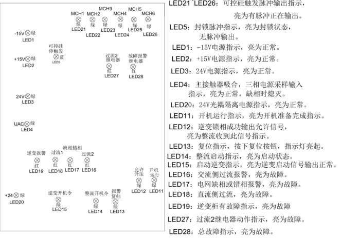
Rectifier Board LED Instructions
LED1: -15V power supply indicator. Light on means on normal state.
LED2: +15V power supply indicator. Light on means on normal state.
LED3: 24V power supply indicator. Light on means on normal state.
LED4: Indicator of Main contactor pull in and the 3 phase power supply input. Light on means on normal state, light off is lack of phase.
LED5: Lock Pulse indicator. Light on when on lock status.
LED20: 24V isolation power supply indicator. Light on means on normal state.
LED11: Welder running indicator. Light on means welder ready.
LED12: Inverter phase lock successfully, output is allowed. Light on shows DC cabinet received this indication.
LED13: Reset indicator. Press the button "RESET", this LED light on.
LED14: Rectifier start indicator. Light on means on start state.
LED15: Inverter start indicator. Light on means the inverter output on normal state.
LED16: AC side over current alarm. Light on means Fault.
LED17: Lack phase or wrong phase alarm. Light on means Fault.
LED18: DC side over current alarm. Light on means Fault.
LED19: Inverter fault indicator. Light on means Fault.
LED21-LED26:SCR pulse Output Indicator. Light on when on output status.
LED27: Relay of over current 2 action indicator. Light on means Fault.
LED28: Entire Fault indicator. Light on means Fault.