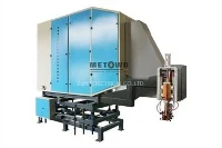
In addition, it is well known that the loss of inverter device is divided into the on-state loss and switching losses. The on-state loss = tube voltage drop * operating current. Because the SCR has four-layer structure, and IGBT has 2 layers, so the on-state loss is small. Switching loss refers to the loss during turn-on and turn-off. The size of the switching loss depends on the operating current during switching and the switching time. Just like vehicle weight and braking distance in the event of braking, the shorter the distance, the smaller the loss for the same vehicle. Similarly, the shorter the switching time is, the smaller the switching losses of the device are. Because the turn-on time is very short, the loss is mainly the switching loss. As mentioned above, the SCR has about 8US in fastest time, and the IGBT is less than 1US. Therefore, the switching loss varies widely. In another word, theswitching loss of the IGBT is also much smaller than that of the SCR.
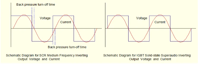
Another point is that a special phenomenon exists in the SCR medium frequency, that is, inverter failure. It can be seen from the voltage and current phase diagram shown above that the SCR can only work in the capacitive condition, that is, sufficient back pressure time must be retained, so that the inverter bridge can be reliably commutated. In addition, many factors affect the turn-off time, including the operating current, ambient temperature and back pressure level. These factors are likely to change when the device is working properly. So, the failure of oscillation will occur. The IGBT is a automatic turn-off device. It is turned on in the presence of pulse, and turned off in the absence of pulse, without back pressure time and inverter failure. It means that the IGBT device has the 100% success rate of start. However, the success rate of start of the SCR cannot be guaranteed.