


The core of a device is its control system. The level of the control system determines the quality of the product. The control system of the company's IGBT solid-state power uses a combination of hardware and software, which gives computer advantages into full play to enable the equipment to operate more stable and reliable . In summary, the main points are as follows:
1. Features of rectification section control
1.1 The rectifier control system uses two 89C51 single chip microcomputers for control. One is used as digital trigger to complete the voltage regulation function, and the other one is used for protection of fault chain and inverter control system communication. This overcomes the shortcomings of redundant computer program and busy work, and increases the rapidness of protection action.
1.2The digital phase-locked technology is adopted to make the trigger pulse phase move with the fluctuation of grid voltage, thus ensuring constant output voltage.
1.3Trigger pulse maintains equal spacing trigger to minimize the non-characteristic harmonic wave and reduce the pollution to the power grid.
1.4Fault protection uses seal ring protection and push inverter protection, so that the energy stored in the energy storage elements (inductor and capacitor, etc.) is fed back to the power grid.
1.5Rectifier pulse phase shift scope is 150 degrees, so that the push inverter protection is more extensive and reliable.
1.6The control circuit owns soft start, soft stop and other functions, which can reduce the impact of du/dt (voltage rise rate) and di/dt (current rise rate) on the IGBT, so that the start and stop operations can be performed frequently.
1.7It can monitor a wide range of faults, such as water shortage, default phase, overvoltage, overcurrent, fusing, and drive undervoltage. The LED digital block displays the operating status, which facilitates maintenance.
1.8The control circuit, main circuit and heating circuit are interlocked respectively to avoid damage to equipment in spite of misoperation, thereby reducing the failure rate.
1.9 A/ D value detection uses the interrupt mode (80 microseconds per time) to speed up the response time.
1.10Hence, the communication with the inverter control system is increased, making the start and protection more stable and reliable.
2. Features of gradient section control
2.1 The method of separate excitation to self-excitation is used for start. The success rate of start is 100%.
2.2For acquisition of signal, the LM319 (military) is adopted, instead of the traditional LM339, which increases the signal speed and reliability, but also facilitates TTL circuit interface.
2.3The excessive large lead angle of the parallel resonant circuit will result in excessive low power factor and high oscillation voltage.
The excessive large output current (mainly reactive current) will cause damage to the IGBT in serious case. However, excessive low output current, due to the proximity of the inductive region, will cause the IGBT to generatevoltage spike at the moment of turn-off. It is difficult to absorb the voltage spike simply by resistance. If the spike is too high, it will also damage the IGBT. So, it is sure to keep the trigger lead angle constant. The control system uses phase-locked and frequency-locked technology; the phase detector uses the falling edge of current and voltage phase for phase demodulation, so it is more reliable and fast compared with the average phase-detector filter average; the voltage-controlled oscillator uses INTEL oscillator ICL8038, which is characterized by goodfrequency signal linearity, small temperature drift and high accuracy. The specific block diagram is shown below:
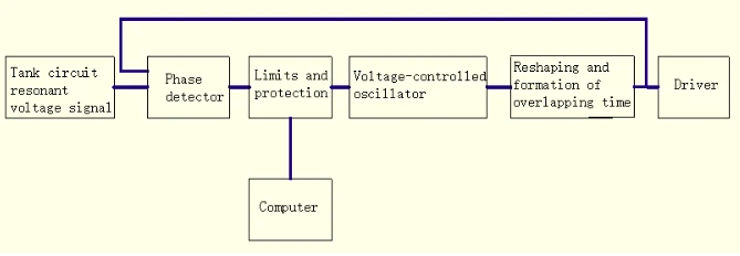
2.4The purpose of phase lock is to lock the phase of voltage and current waveforms. If the load is short-circuited, the voltage feedback signal will disappear, the phase detector will not be capable of phase discrimination, and the oscillation voltage of the voltage-controlled oscillator will reach the limit. As a consequence, the resonance status will be seriously out of tune, causing damage to the IGBT. The detuning protection circuit designed by the company will detect the aforesaid conditions. In the event of detuning, automatic protection and digital display will occur.
2.5 Range of phase lock:
Due to use of the falling edge for phase approach, the phase locking has a wide scope up to 3 times the scope. For instance, if the minimum operating frequency is set to 8kHZ, the device operating frequency scope can be any frequency within 8-24kHZ, which covers the superaudio frequency and intermediate frequency. As a result, one machine can be used as two machines.
2.6The computer with frequency display function has very high accuracy and small display error in the number of pulses.
3. Driving section
The drive signal from the control circuit is isolated. The power sources of each drive board are also isolated from each other. The falling edge of the drive pulse is calibrated. In this way, the diagonal pulse of the IGBT is strictly consistent, making commutation safer and more reliable.


