
Latest Products





Contact Us

CHINA
ADD: ChaoYangNan Str, 300m to BaoCang Express Way Exit, BaoDing, HeBei, China
TEL: +86-312-2090169/2090165
FAX: +86-312-2090165
Email: sales02@metowd.com

IRAN
ADD: No.3 - Golshid9 St. - Nakhlestan Blvd. - Shams abad industrial Zone -40km Tehran Qom Freeway - Tehran - Iran
Postal Code: 1834175977
Tel: 00982156231607-8
Mob: 00989121350509
Email: atiravesh@yahoo.com

Germany Design & Development Office
Germany Design & Development Office
ADD: Wellensiek 111, 33619 Bielefeld Deutschland, Germany
Tel: 0049 521 9890 170
Mob: 0049 163 5149 622

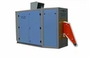
Complete Equipment For Solid-state Superaudio Steel Pipe Annealing
1.For GCYP series solid-statesuper-audio equipment, its model meanings are as follows: 2. GCYP series solid-statesuper-audio equipment adopts the modern power electric device IGBT (insulate-gate bipolar transistor) module as the key device of inverter. Its control system is consisted of...
Description

1.For GCYP series solid-statesuper-audio equipment, its model meanings are as follows:

2.
GCYP series solid-statesuper-audio equipment adopts the modern power electric device IGBT (insulate-gate bipolar transistor) module as the key device of inverter. Its control system is consisted of rectifying circuit, power regulating circuit, protection circuit and control circuit, advanced frequency tracking and constant angle inverter triggering and optimized IGBT-driven protection circuit. The equipment has many advantages, such as high efficiency, simply and reliable circuit, convenient debugging and operation, not only improving the production process of the manufacturing enterprises, but also obviously improving the energy-saving effect.
GCYP series solid-statesuper-audio equipment is a super-audio power supply that converts three-phase alternating current with the industrial frequency of 50 Hz into the single phase alternating current (7-50 kHz), which can be widely used in metal melting, welding, heat transfer, quenching and other heat processing and treatments.
3.Operating environment
①For indoor installation, the equipment shall be well grounded, the color of the grounding line must be obviously different from that of the control line, its sectional area is larger than 4 mm2, and the grounding resistance is not larger than 4 Ω;
②The altitude should not exceed 1,000 meters; Otherwise, the rated value should be reduced;
③The ambient temperature should be not higher than +40℃, and not lower than -10℃;
④The relative humidity of air shall be no more than 85%;
⑤No violent vibration, no conductive dust, no corrosive gases and explosive gases;
⑥The installation gradient shall be not more than 5°.
⑦The equipmentshall be installed in the position with good ventilation.
4.
Requirements for cooling water
The power supply device, load sensor, busbar and other units should adopt water cooling. The quality of the supplied cooling water directly affect the reliability of the equipment operation. Therefore, it is suggested to analyze and test the cooling water, and the result should meet the following conditions. If there is any difference, it should be solved through relevant purification methods.
①Mechanical properties
Transparent, not turbid, and free from precipitate (mesh size of 0.38 mm), and the total solid content should not exceed 250 mg/L;
②Chemical properties
|
PH value should be |
Between 6 and 8 |
|
Chloride |
Not larger than 100 mg/L |
|
Nitrite (NO2) |
Not larger than 0.04 mg/L |
|
Iron |
Not larger than 0.3 mg/L |
|
Manganese |
Not larger than 0.05mg/L |
|
Sulfur |
Not larger than 250 mg/L |
③Electrical conductivity: Not larger than 600 μs/cm
④Temperature of inlet water: Between 5 ℃ and 35 ℃. When being used in hot weather and the conditions with high relative humidity, the water inlet temperature must ensure that there is no condensation on the surface of the water-cooled elements;
⑤Pressure of inlet water: 0.18-0.35 MPa (about 1.8-3.5 kg/cm2).
5.Requirements for power grid
The power grid voltage should be sine wave, and the harmonic distortion is not larger than 5%. If the alternating voltage with the line voltage of 380 V - 415 V, the continuous fluctuation range of the power grid voltage does not exceed ±10%, the frequency change of the power grid does not exceed ±2%, and the degree of unbalance between three-phase voltages should be less than ±5%.
6.Specifications and model
(1) The rated input power supply of the equipment
For the three-phase four-wire alternating current, its frequency is 50 Hz, and the line voltage is 380 V-415 V.
(2) The nominal values of the GCYP series solid-state super-audio equipment are shown in Table
|
Technical parameters Specifications and model |
Rated DC voltage (V) |
Rated DC Current (A) |
Rated DC power (kW) |
Maximum DC voltage (V) |
Maximum DC current (A) |
Maximum DC power (kW) |
|
GCYP-30/7~50 |
450 |
70 |
31.5 |
500 |
80 |
40 |
|
GCYP-50/7~50 |
450 |
115 |
51.8 |
500 |
120 |
60 |
|
GCYP-75/7~50 |
450 |
170 |
76.5 |
500 |
180 |
90 |
|
GCYP-100/7~50 |
450 |
230 |
103.5 |
500 |
240 |
120 |
|
GCYP-160/7~50 |
450 |
360 |
162 |
500 |
380 |
190 |
|
GCYP-200/7~50 |
450 |
450 |
202.5 |
500 |
480 |
240 |
|
GCYP-250/7~50 |
450 |
560 |
252 |
500 |
600 |
300 |
|
GCYP-320/7~50 |
450 |
720 |
324 |
500 |
740 |
370 |
|
GCYP-400/7~50 |
450 |
900 |
405 |
500 |
920 |
460 |
|
GCYP-500/7~50 |
450 |
1120 |
504 |
500 |
1200 |
600 |
|
GCYP-800/7~50 |
450 |
1800 |
810 |
500 |
1840 |
920 |
7.Requirements for power supply wiring
(1) The inlet wires of the equipment power supply are connected by copper power cables, and is connected with the load by the copper bar or several twisted pairs. The contact at the connection place should be good and reliable, the contact area should be increased as much as possible, and the contact resistance should be reduced.
(2) There are requirements to distinguish the phase sequence of the inlet wires of the power supply. The inlet wires must be connected in positive sequence, and A, B, and C inlet wires should be connected to yellow, green and red respectively and marked with obvious signs.
(3) The connector lugs of the inlet wires of the power supply should be firmly pressured, treated with tin, and fastened with screws. The nominal current value of the connector plugs should not less than 0.816 times of the maximum direct current value under the power shown in Table 1.
(4) The sectional area of the inlet wires of the power supply and that of the copper bar or twisted pairs connected with the load should not less than the values listed in Table
-
(1) The inlet wires of the equipment power supply are connected by copper power cables, and is connected with the load by the copper bar or several twisted pairs. The contact at the connection place should be good and reliable, the contact area should be increased as much as possible, and the contact resistance should be reduced.
8.Table 2.Value of Sectional Area of Inlet Wires of Power Supply and that of Copper Bar connecting with the Load
|
Rated power (kW) |
Sectional area of three-phase copper inlet wires (mm2) |
Sectional area of the copper bar or twisted pairs connecting with the load (mm2) |
|
30 |
35 |
80 |
|
50 |
50 |
100 |
|
75 |
70 |
120 |
|
100 |
95 |
160 |
|
160 |
120 |
200 |
|
200 |
185 |
240 |
|
250 |
240 |
300 |
|
320 |
300 |
360 |
|
400 |
2×185 |
400 |
|
500 |
2×240 |
500 |
|
800 |
2×300 |
2×400 |
9.Electrical Composition and Principle
The main circuit structure of the GCYP series solid-state super-audio induction heating power supply is shown in Figure 1. The rectifier adopts a three-phase full-controlled rectifier bridge circuit that is consisted of thyristors. The inverter adopts the single-phase bridge inverter circuit that is consisted of IGBT, and the load is in parallel resonance structure.

10.
Three-phase full-controlled rectifier bridge
The three-phase full-controlled rectifier bridge circuit is shown in Figure 2. The function of this circuit is to convert three-phase alternating current to direct current.
Figure 2Structure of Three-phase Full-controlled Rectifier Bridge Circuit

11.
Composition and principle of rectifier trigger, control and protection circuit
The main function of the rectifier triggering and control circuit is to generate the six-way phase-shift trigger pulse required by the three-phase full-controlled rectifier bridge circuit. The form of the trigger pulse is a double narrow pulse trains. The circuit consists of a three-phase synchronization, trigger circuit, power-driven, current and voltage dual closed-loop PI regulation control circuit, start and peak voltage detection, leakage detection and various protection circuits.
In order to stabilize the welding quality, the phase-shift triggering control adopts current and voltage double closed-loop feedback control technology to provide a constant power output.
When the equipment stops working or overcurrent, overvoltage and other any warnings occur, the control system allows three-phase full-control rectifier bridge to quickly enter the inverter working state to discharge the energy stored in the smoothing reactor and return it to the power grid, avoid the counter potential formed leading to too high inverter input end voltage to break down the inverter bridge IGBT switching elements for achieving the purpose of the working safety and protection of the equipment.
To reliably trigger the thyristor, this equipment uses a dual spike pulse train triggering form, effectively reducing the pulse transformer volume and load; The leading-edge current rate of change of the triggering pulse is larger than 1A/(S to effectively trigger the thyristor without considering the dispersibility of its triggered current.
12.
Parallel resonance single-phase inverter bridge circuit
The inverter uses the parallel resonance structure form, and its basic circuit structure is shown in Figure 3. IG1~IG4 in the figure compose the single-phase bridged inverter circuit. Due to no reverse blocking capacity in IGBT, serial fast recovery diode of each bridge arm (VD1~ VD4) bears the backward voltage, L and r are equivalent inductance and resistance for inductors and load, C is compensation capacitor, and L, C and r compose the parallel resonance circuit. Under the control of the frequency tracking and inverter control circuit, IG1, IG4 andIG2, IG3 and tank circuit resonance frequency synchronize rolling breakover, converting DC into AC- inversion.
Figure 3Schematic Diagram of Parallel Resonance Single-phase Bridge Inverter
In order to achieve fast blocking capability, fast recovery diodes are required for series diodes VD1 - VD4.
13.
Frequency tracking and inverter trigger control
Inversion is a basic form of transformation and control of electrical energy. The function realized by the solid-state super-audio induction heating power supply (or induction heating device) is an AC to DC to AC power conversion process, and DC to AC is a frequency conversion process, also called as inversion. Solid-state super-audio induction heating power supply is a device that using inverter technology to generate a certain frequency of alternating current, thereby generating alternating magnetic field, causing metal generating eddy current in the alternating magnetic field, so as to achieve the purpose of induction heating. The frequency tracking and inverter triggering control are the core of inverter control that converts DC power into AC power and is the key to inverter control technology.
The function of inverter control is to realize the inverter startup, automatic tracking of the load resonance frequency, and to generate and provide reliable driving trigger pulses for the inverter power device. When the control circuit of the rectifier side is used for the abnormality occurring inside or outside the equipment, controlling the working status of the rectifier bridge can ensure equipment safety.
14.
Protection function
The protection circuit is the basic guarantee for the safe operation of the induction heating power supply equipment and plays a very important role in the control technology of the power supply. The protection function of the equipment is designed for various abnormal conditions and faults. The power supply is provided with phase loss, phase error, water pressure, IGBT temperature, overcurrent, over voltage, peak voltage, leakage current, frequency overrun, and control board work. Voltage monitoring and other protection functions. IGBT drive protection includes: Operating voltage, pulse loss, IGBT overcurrent, etc.,making equipment work safer, failure rate, damage rate lower to the minimum.
15.
Equipment Installation and Requirements
(1) After the equipment is unpacked, it is necessary to check whether the components fall off by shock, and are dampened during transportation. If the above conditions are found, they shall be repaired and used after the defects are eliminated. Please inform the company in time so as not to miss the claim time.
(2) The equipment shall be installed in a well-ventilated room that is not subject to rain, and shall keep a certain distance from the wall.
(3) Check the waterway, water temperature, water quality, water pressure shall meet the cooling water requirements of the equipment , check whether the connection points of the water pipe are loose and disconnected, whether the water pipe is broken or blocked, and the leakage of water inside the machine is strictly prohibited. If the above conditions are not met, they shall be repaired before use.
(4) Before use, check whether the electrical circuit is in good condition, whether the components are damaged, and whether the contact points and the connection terminals are loosened or disconnected. If any of the above conditions occurs, eliminate the failures before use.
(5) According to the use instruction of the external terminals provided on the drawing of the equipment, connect the external control lines and check whether the external lead connection is correct, whether the requirements are met, and whether the connection points are loose. Power lines and control signal lines must be laid separately to prevent interference. The control signal line must penetrate through the metal pipe to connect between devices.
(6) The equipment housing (including main cabinets, consoles, and capacitor cabinets, etc.) must be well grounded to prevent electric shock and improve the equipment's anti-interference ability.
anti-interference ability. Grounding requirements refer to 9.2.
(7) According power connection requirements, connect the power incoming lines and load. The cross-sectional area of the power line and the copper bar or twisted pair connected to the load shall not be less than the values and requirements listed in Table 2.
(8) Make the appropriate sensors for the heated workpieces, and connect them with the tank output.
16.
Operating Procedures and Precautions
(1) Open the cooling water system, when the water pressure meets the requirements (0.18-0.35MPa, approximately 1.8-3.5kg/cm2), the contact of the water pressure gauge is in the open state (the contact of the water pressure gauge when the water pressure is too low or too high, it is in the closed state), check the water flow in the outlet pipe and check whether the cooling water pressure and the water quality meet the requirements. Check for water shortages and leaks.
(2) Check tank and sensor: Check if there is a short circuit between the heated workpiece and the sensor, and if the sensor has open circuit or short circuit.
(3) After power transmission, check whether the line voltage indicated by the line voltage meter on the main cabinet panel is normal.
(4) After turning the "Control Power" knob clockwise, the green indicator on the main control board, inverter trigger control board and IGBT driver board lights up; After the power transmission, the "Fault Indicator" light is on. Press the "Reset" button to reset. Then, proceed to the next step.
(5) Turn the "Power Adjustment" knob counterclockwise to the minimum position; After the power transmission to each control board is stabilized, press the "Main Circuit Start" button, the main contractor is connected, and the "Main Circuit Start" button is on.
(6) The equipment is in the working state that can start heating at any time, and after pressing "Heating Start" button, the heating relay J2 operates. First of all, the initial DC voltage is set up automatically, DC voltmeter indicates the voltage value ranging from 20 to 30 V, and after the time-delay relay delays 1-2 seconds before the heating relay J3 operates, "Heating Start" button indicator light is on, "START" green indicator light on the inverter trigger panel is on, and power supply automatically enters the self-oscillating resonance working state for frequency tracking while "SYNC" green indicator light on the inverter trigger panel is on. "DC voltage", "DC current" meters will also have a corresponding indication. Adjust the "Power Adjustment" knob to the desired power position to perform normal induction heating.
17.Shutdown process
The shutdown process follows the reverse operation sequence of the boot process. The following points shall be noted:
①The shutdown process must be performed in the order of "Stop Heating" → "Stop Main Circuit" → "Stop Control Power Supply" → "Stop External Switchgear Cabinet Power Supply". Because of the interlocking control between heating control, main loop control and control power supply operation
②After pressing the "Stop Heating" button, the equipment stops working and the power output is zero.
18.Precautions for use
①When replacing the heated workpiece specification, attention must be paid to the matching problem between the sensor and the workpiece. When the size of the heated workpiece is greatly different, it is better to replace the matched sensor to improve the efficiency and output capability of the device.
②Regularly check the waterways of the equipment for any abnormal phenomena such as water leakage or water plugging, and ensure that the cooling water channels are open.
③Frequently check whether the indicators, hands, indicators are normal, including DC voltmeter, DC ammeter, AC voltmeter, etc.;
④Keep the control circuits and devices in the cabinets clean.
⑤Take multiple protection measures for the equipment. When a fault occurs, the protection circuit operates. The "Fault Indicator" on the panel and control panel (including: The corresponding red LEDs on the main control board, inverter trigger control board, and IGBT driver board are onPlease do not rush to perform reset operations.Carefully observe and record the content of the alarm and analyze the cause of the fault. Power on after processing,and avoid blind operations in order to prevent the fault from expanding.
19.
The reference drawing for construction of equipment grounding system
For the construction drawing of equipment grounding system, refer to Figure 4.

Hot Tags: complete equipment for solid-state superaudio steel pipe annealing, China, manufacturers, suppliers, factory, customized, wholesale, buy, made in China, pipeline welding machine, newest separate cabinet high efficiency welder, High Frequency Induction Heating Equipment, ERW Steel Pipe Welding Equipment, solid state welder, ERW Tube And Pipe Welder
You Might Also Like


